OSPF DR and BDR
Course Contents
1. Introduction
OSPF needs to elect a DR (Designated Router) and a BDR (Backup Designated Router) to function efficiently on multi-access networks.
Why are OSPF DR and BDR necessary?
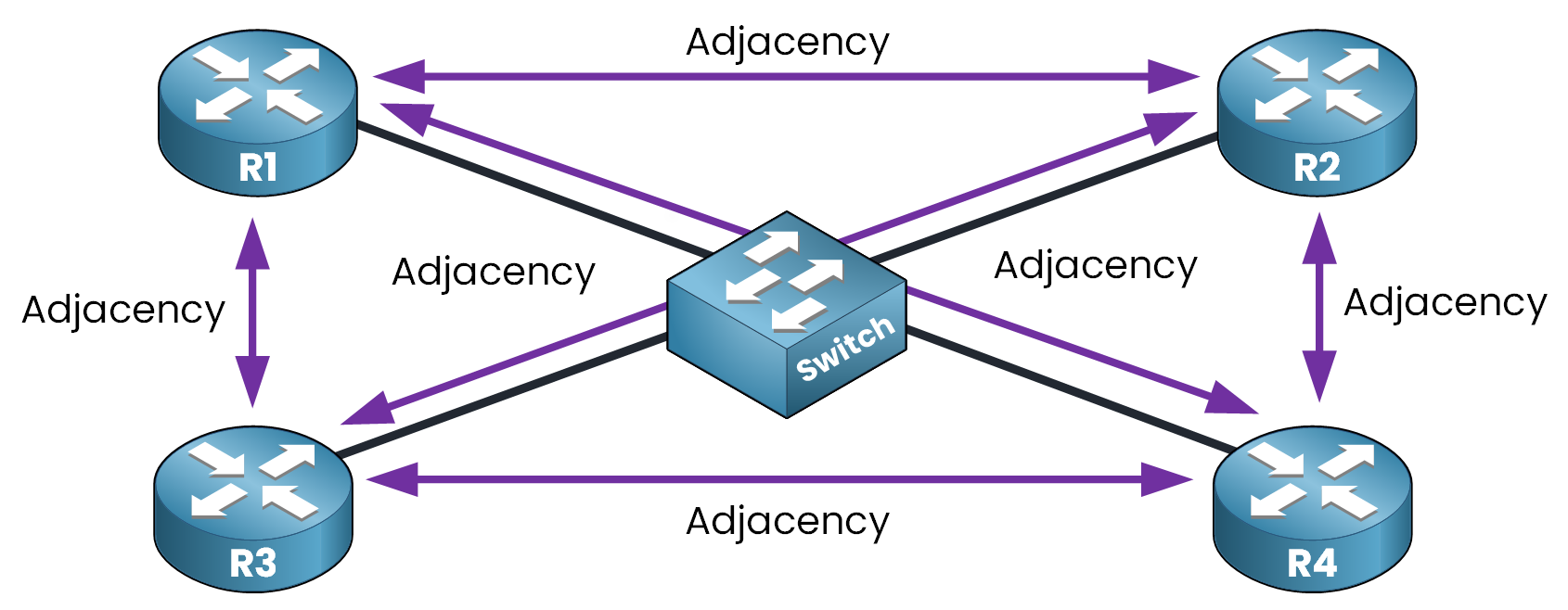
On multi-access segments (such as Ethernet), many routers can be connected to the same network as shown below. When each router tries to form OSPF neighbor adjacencies with every other router, the number of relationships increases rapidly.
The number of adjacencies grows according to the formula:
n(n – 1) / 2, where n is the number of routers.
In the example above, we have 4 routers:
4(4 – 1) / 2 = 6 adjacencies
Now imagine a larger segment with 10 routers:
10(10 – 1) / 2 = 45 adjacencies
This quickly becomes inefficient.
More routers means:
- More OSPF neighbors to maintain
- More LSAs exchanged between devices
- More CPU and memory consumed to keep OSPF running
That’s exactly why OSPF DR and BDR were introduced to reduce adjacency overload and improve scalability on multi-access networks.
2. Without a DR/BDR
Imagine a network without a DR or BDR.
When a router like R1 joins the segment, it sends LSAs to 224.0.0.5 (All OSPF Routers).
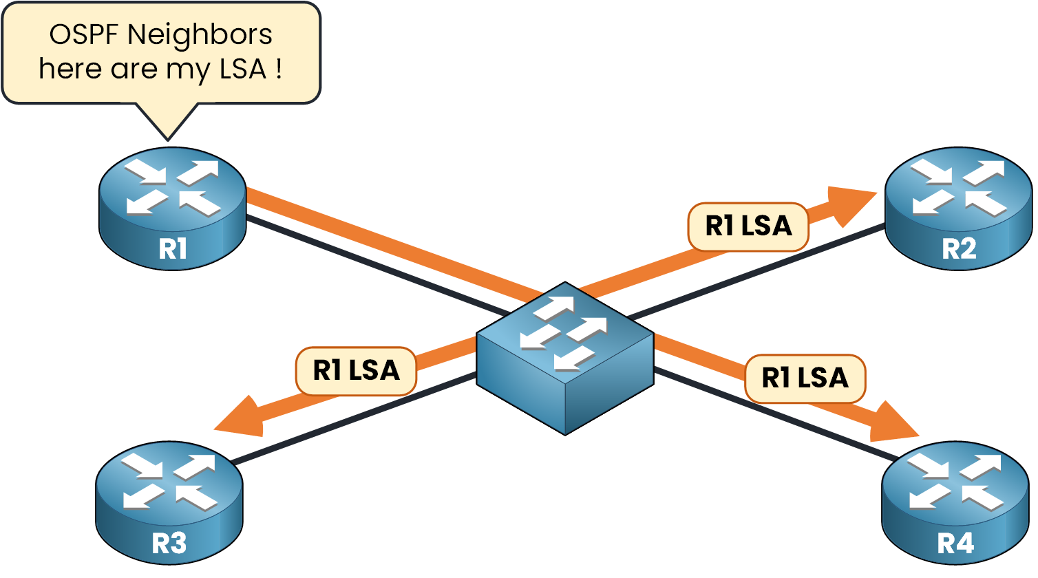
All other routers on the segment (R2, R3, R4) receive this LSA, acknowledge it, and then re-flood it to the others again to 224.0.0.5.
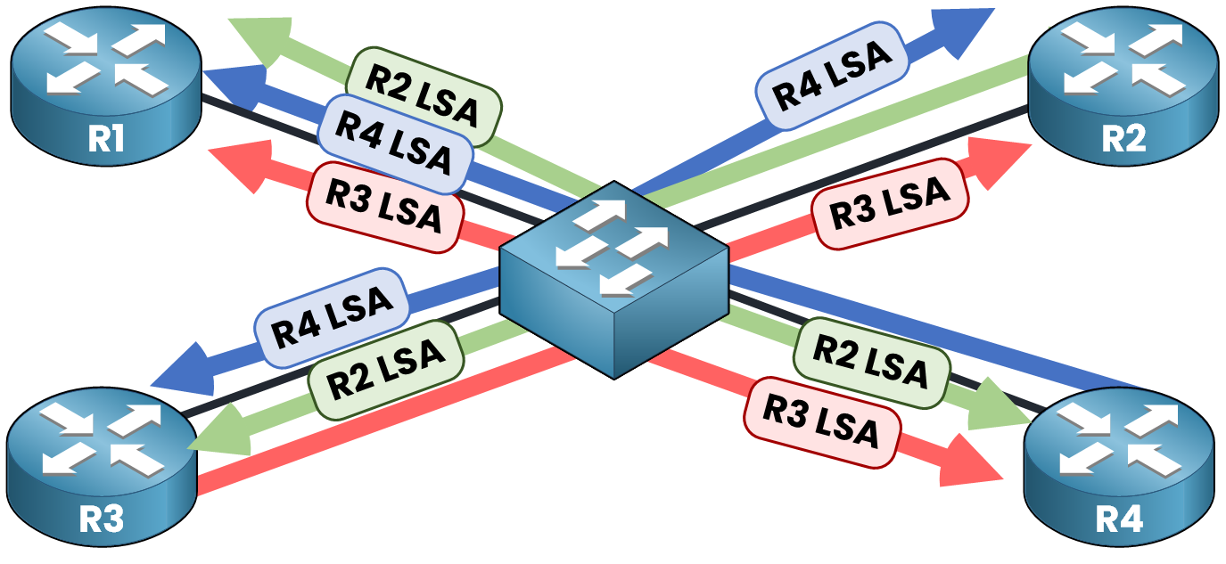
This creates a storm of redundant LSAs, especially when multiple routers advertise new information. It wastes bandwidth and CPU.
To solve this issue, OSPF introduces the concept of a DR (Designated Router) and BDR (Backup Designated Router).
The concept is very simple, the DR collects all the LSA and sends the LSA one time to all other routers. The BDR act as a Backup when the DR fails and takes its place.
3. With a DR/BDR
With a DR and BDR elected:
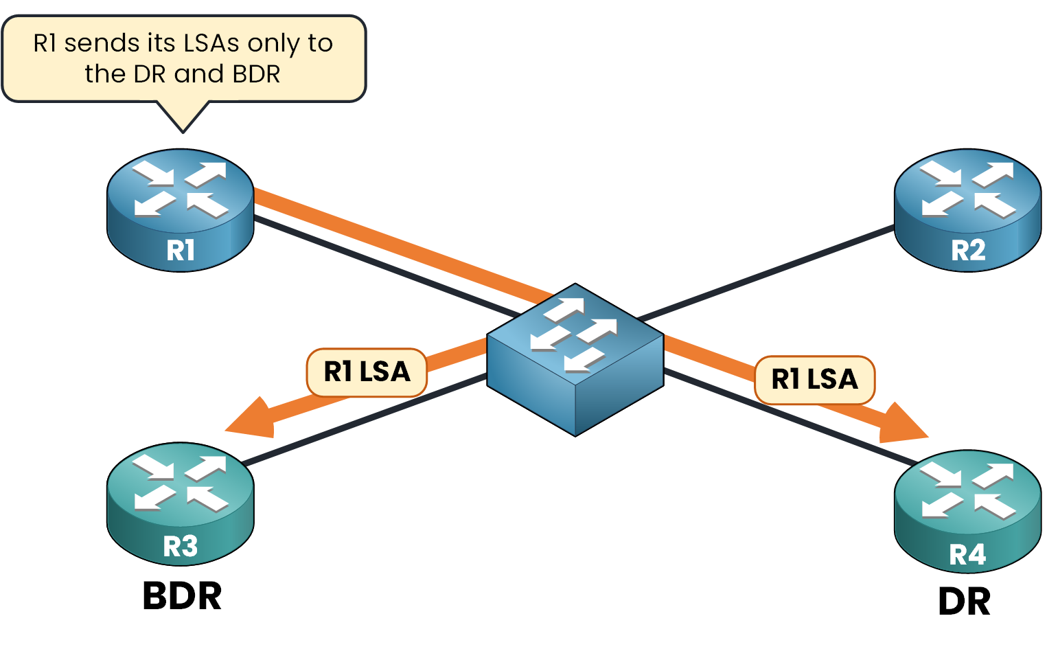
- R1 forms adjacencies with the DR and BDR
- When R1 generates an LSA, it sends it only to 224.0.0.6 (All Designated Router).
Then:
- The DR forwards the LSA to all other routers using 224.0.0.5
- The BDR is ready to take over if the DR fails
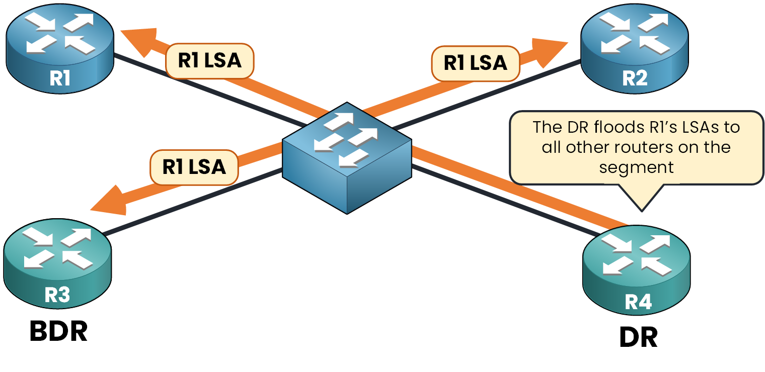
The LSA is flooded only one time and every router learns about it without unnecessary duplication.
To achieve this behavior, OSPF performs a DR/BDR election.
4. DR/BDR Election
In OSPF, the DR/BDR election takes place on multi-access networks (like Ethernet), not on point-to-point links.
Where Does the DR/BDR Election Happen?
This election happens after the 2-Way state during OSPF neighbor formation.
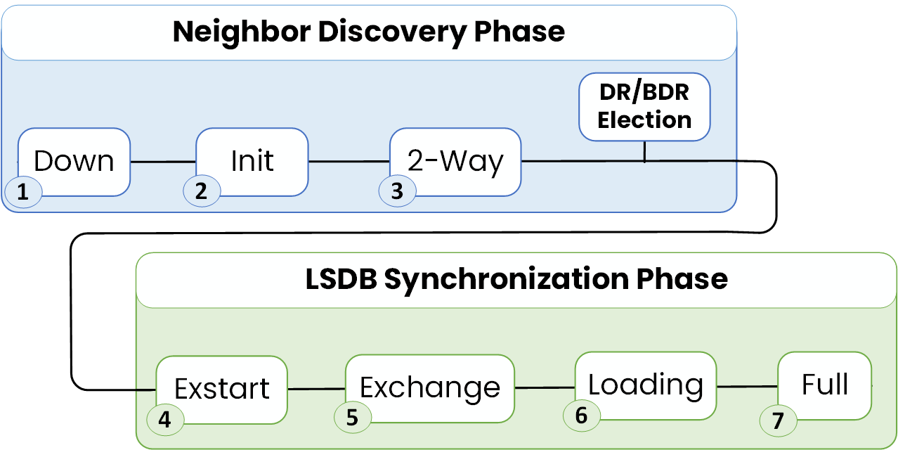
The Election only occurs on multi-access networks. If the interface is configured as a point-to-point link, there’s no DR and BDR election.
Each OSPF router checks the network type on its interface and determines if it needs to participate in the DR/BDR election.
DR and BDR Election Rules
The DR and BDR routers are selected based on OSPF priority and Router ID:
Election rules
- The router with the highest priority becomes DR
- The second-highest becomes BDR
- If equal, the highest Router ID wins
- A router with priority 0 is not eligible
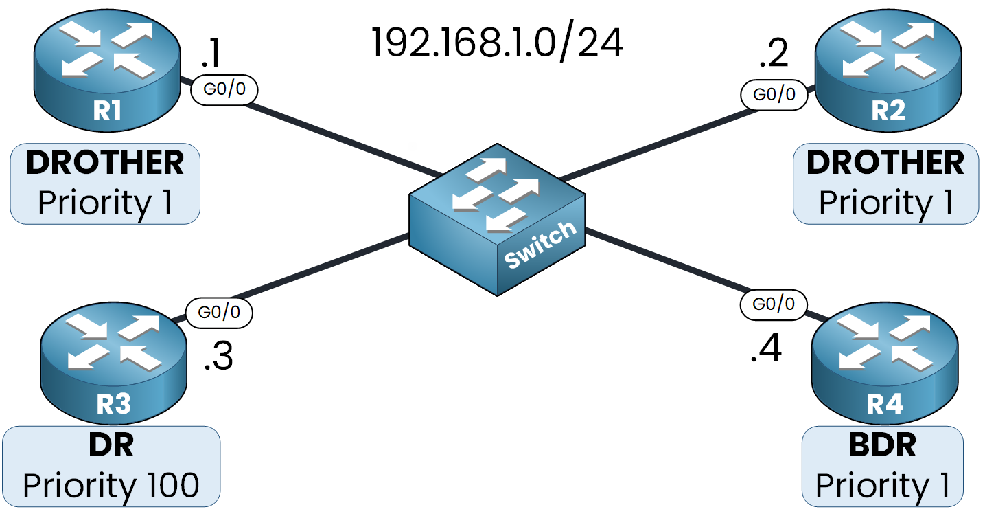
In this example:
R4 (priority 100) → DR
R3 (priority 1 and have the Highest Router ID 192.168.1.4) → BDR
R1 and R2 → not elected → become DROTHERs
5. Understanding DROTHER
A DROTHER is a router that is not elected as DR or BDR.
What does a DROTHER do?
- A DROTHER forms a FULL adjacency only with the DR and BDR.
- It forms a 2-WAY state with other DROTHERs.
Example: Neighbor Table on R1
R1# show ip ospf neighbor

Neighbor ID   Pri    State        Dead Time  Address      Interface
192.168.1.4    1     FULL/BDR     00:00:24   192.168.1.4  GigabitEthernet0/0
192.168.1.3    100   FULL/DR      00:00:24   192.168.1.3  GigabitEthernet0/0
192.168.1.2    1     2WAY/DROTHER  00:00:24   192.168.1.2  GigabitEthernet0/0
- R3 has priority 100 and is elected DR.
- R4 is the BDR.
- R2 is a DROTHER.
From R1’s perspective, it has:
- FULL adjacencies with R3 (DR) and R4 (BDR)
- Only a 2-WAY state with R2 (another DROTHER)
This mechanism limits the number of adjacencies and controls LSA flooding.
Now that you understand how OSPF DR and BDR work and why they’re important, let’s see how to configure them in a real lab scenario.
6. Lab: Configure OSPF DR and BDR
In this lab, we are going to configure R3 as the Designated Router (DR) and R4 as the Backup Designated Router (BDR) on a shared Ethernet segment.

Our topology includes four routers:
- R1: 192.168.1.1
- R2: 192.168.1.2
- R3: 192.168.1.3
- R4: 192.168.1.4
All routers are connected to the 192.168.1.0/24 subnet through their GigabitEthernet0/0 interface.
Step 1 – OSPF Configuration on All Routers
On each router, we enable OSPF and advertise the shared network:
router ospf 1
network 192.168.1.0 0.0.0.255 area 0
This network includes the G0/0 interface in OSPF and immediately triggers the DR/BDR election.
Step 2 – Checking the Initial Election
At this stage, we have not configured any OSPF priority. All routers are using the default priority of 1.
When priorities are equal, OSPF uses the highest Router ID to elect the Designated Router (DR). The router with the second-highest ID becomes the Backup Designated Router (BDR).
In our case:
- R4 has the highest Router ID: 192.168.1.4 → elected as DR
- R3 has the next highest Router ID: 192.168.1.3 → elected as BDR
On R1 we can verify by using this command:
R1# show ip ospf neighbor

Neighbor ID      Pri  State          Dead Time   Address      Interface
192.168.1.3       1   FULL/BDR   00:00:23    192.168.1.3  GigabitEthernet0/0
192.168.1.4       1   FULL/DR    00:00:23    192.168.1.4  GigabitEthernet0/0
192.168.1.2       1   2WAY/DROTHER   00:00:23    192.168.1.2  GigabitEthernet0/0
We can see Neighbor ID 192.168.1.3 which is R3 viewed as the BDR and Neighbor ID 192.168.1.4 as R4 is viewed as DR.
Step 3 – Forcing R3 to Become the DR
To change the election outcome and make R3 the new DR, we can increase its OSPF priority to 100 for example.
R3# configure terminal
R3(config)# interface g0/0
R3(config-if)# ip ospf priority ?
  <0-255>  Priority
R3(config-if)# ip ospf priority 100
Changing the priority alone does not affect the current election. Since OSPF elections are non-preemptive, once the DR and BDR are elected they will not be replaced automatically, even if another router with a higher priority appears.
To trigger a new election, we neeed to manually reset the OSPF process.
Step 4 – Restarting OSPF
To force a re-election, we clear the OSPF process on R3:
R3# clear ip ospf process
Reset ALL OSPF processes? [no]:  yes
This command resets all adjacencies and triggers a new DR/BDR election.
%OSPF-5-ADJCHG: Process 1, Nbr 192.168.1.4 on GigabitEthernet0/0 from FULL to DOWN, Neighbor Down: Adjacency forced to reset
%OSPF-5-ADJCHG: Process 1, Nbr 192.168.1.1 on GigabitEthernet0/0 from FULL to DOWN, Neighbor Down: Adjacency forced to reset
Step 5 – Verifying the New Election
After OSPF reconverges, we can check again from R1:
R1# show ip ospf neighbor

Neighbor ID   Pri    State        Dead Time  Address      Interface
192.168.1.4    1     FULL/BDR     00:00:24   192.168.1.4  GigabitEthernet0/0
192.168.1.3    100   FULL/DR      00:00:24   192.168.1.3  GigabitEthernet0/0
192.168.1.2    1     2WAY/DROTHER  00:00:24   192.168.1.2  GigabitEthernet0/0
R3 is now the DR thanks to its higher priority, and R4 is the BDR.
Step 6 – Confirming DR Role
To confirm from R3:
R3# show ip ospf interface g0/0

GigabitEthernet0/0 is up, line protocol is up
  Internet address is 192.168.1.3/24, Area 0
  Process ID 1, Router ID 192.168.1.3, Network Type BROADCAST, Cost: 1
  Transmit Delay is 1 sec, State DR, Priority 100
  Designated Router (ID) 192.168.1.3, Interface address 192.168.1.3
  Backup Designated Router (ID) 192.168.1.4, Interface address 192.168.1.4
  Timer intervals configured, Hello 10, Dead 40, Wait 40, Retransmit 5
    Hello due in 00:00:00
  Index 1/1, flood queue length 0
  Next 0x0(0)/0x0(0)
  Last flood scan length is 1, maximum is 1
  Last flood scan time is 0 msec, maximum is 0 msec
  Neighbor Count is 3, Adjacent neighbor count is 3
    Adjacent with neighbor 192.168.1.4  (Backup Designated Router)
    Adjacent with neighbor 172.16.1.0
    Adjacent with neighbor 192.168.1.1
  Suppress hello for 0 neighbor(s)
Step 7 – What Happens if the DR Fails?
In OSPF, when the Designated Router (DR) fails, the current Backup Designated Router (BDR) automatically becomes the new DR. Then, a new BDR is elected among the remaining DROTHERs.

Let’s simulate the failure of the DR (R3).
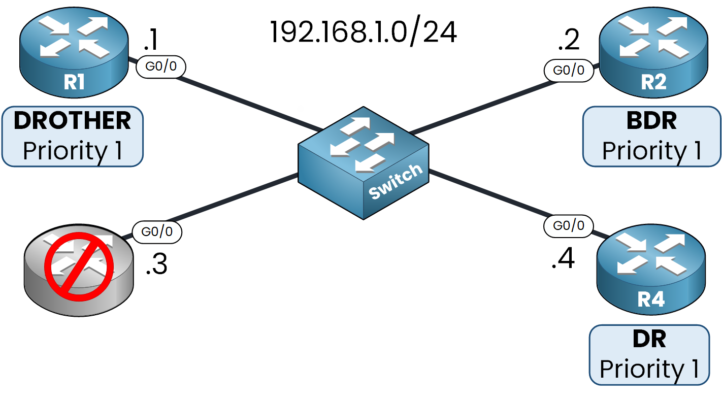
Simulating DR Failure on R3
To simulate a failure, we shut down R3’s OSPF-connected interface:
R3(config)# interface g0/0
R3(config-if)# shutdown
Once the interface is shut down, R3 stops sending Hello packets to its neighbors. However, OSPF doesn’t remove the adjacency immediately. Routers wait for the dead timer to expire by default, 40 seconds.
After this, R4 is promoted to DR, and one of the DROTHERs is elected as the new BDR.
Verifying from R1
Wecan verify the new OSPF neighbor states:
R1# show ip ospf neighbor
Neighbor ID     Pri   State       Dead Time   Address         Interface
192.168.1.4       1   FULL/DR     00:00:35    192.168.1.4     GigabitEthernet0/0
192.168.1.1       1   FULL/BDR    00:00:35    192.168.1.2     GigabitEthernet0/0
- R4 is now the DR
- R2 has become the new BDR
- R3 no longer appears because its adjacency was removed after the dead timer expired
7. Summary
- DR/BDR reduce OSPF overhead on multi-access networks
→ Without them: too many adjacencies (n(n–1)/2)
→ With a DR and BDR: each router only builds adjacencies with the DR and BDR
This drastically reduces the total number of adjacencies.
- LSAs go to DR and BDR only (224.0.0.6)
→ DR floods to all others (224.0.0.5)
- Election rules:
- Highest priority
- If equal → highest Router ID
- Priority 0 = not eligible
- Elections are non-preemptive
- DROTHERs:
→ FULL adjacency only with DR/BDR
→ 2-WAY state with other DROTHERs
- If DR fails → BDR takes over automatically
