LACP EtherChannel is an open-standard protocol defined by IEEE 802.3ad. It allows switches from different vendors to automatically bundle multiple physical links into a single logical connection.
Unlike Static EtherChannel, which relies on manual configuration on both sides, LACP automatically negotiates which interfaces can form the bundle.How LACP Works
Each interface participating in an LACP EtherChannel operates in one of two modes:
Active mode → the switch initiates the negotiation process.
Passive mode → the switch waits for an LACP request before joining the bundle.
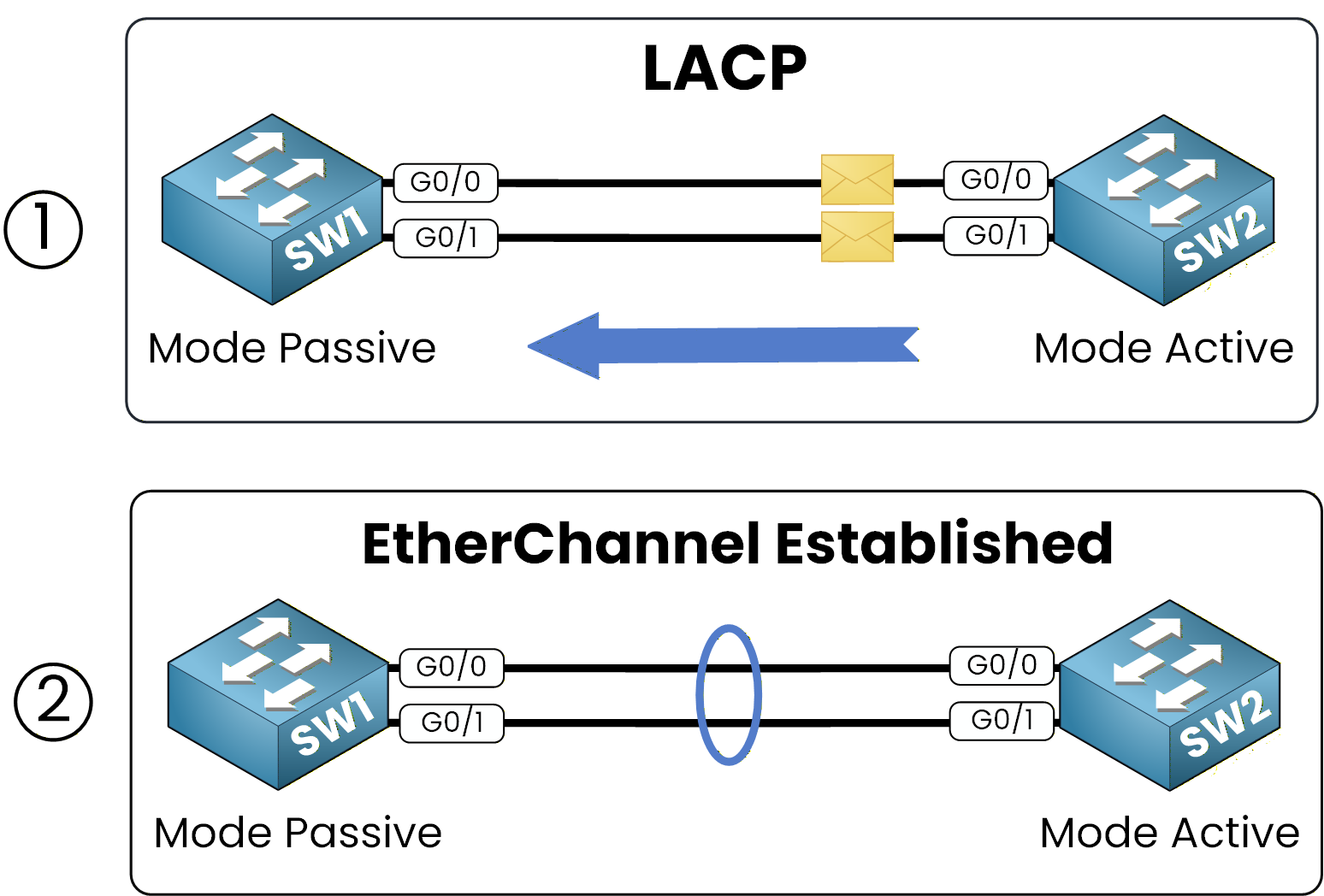
Figure 1 – LACP EtherChannel Using Passive and Active Modes
When one switch runs in Active mode and the other in Passive mode, the EtherChannel forms successfully.
If both sides are Passive, no negotiation starts, and the aggregation does not form.For example, if SW1 uses Passive mode and SW2 uses Active mode, they automatically create a Port-Channel, grouping several physical interfaces into one logical link.
Before You Begin
Before configuring LACP EtherChannel,make sure all participating interfaces meet the following conditions:
Interface consistency: all interfaces must operate with the same speed, duplex, and type.
Trunking or VLAN alignment: for Layer 2 operation, interfaces must share identical VLAN or trunk configurations.
Operational status: each physical link must be active.
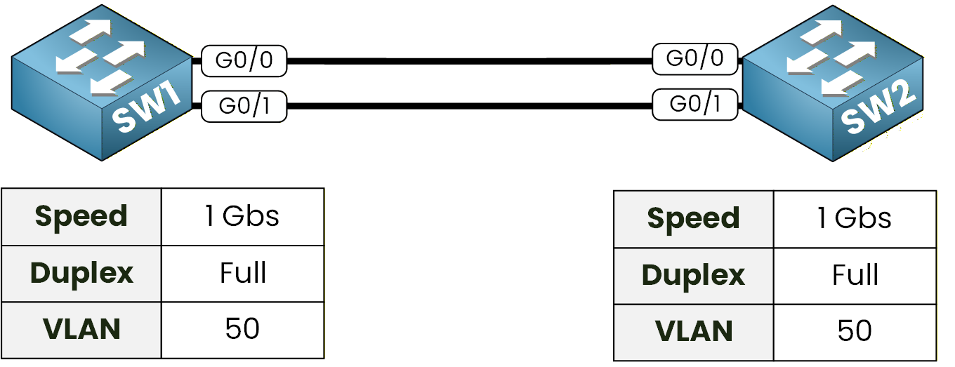
Figure 2 – LACP Link Requirements
If any of these conditions are not met, the EtherChannel will fail to form even with LACP enabled.
Once your interfaces are verified and consistent, you can move on to the configuration phase.For this configuration, we will use GigabitEthernet interfaces running in full-duplex mode, and we will allow VLAN 50 on the trunk link.
Answer the question below
Now that the interfaces are consistent and ready, let’s configure LACP EtherChannel step by step. You’ll define which interfaces participate in the bundle, assign their negotiation modes, and configure the logical Port-Channel as a trunk allowing VLAN 50.
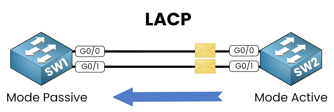
Figure 3 – LACP Configuration Between Passive and Active Modes
Step 1 – Select the Interfaces
Begin by selecting the interfaces that will join the EtherChannel on each switch.
Theinterface rangecommand allows you to configure multiple interfaces at once.On SW1
SW1(config)# interface range g0/0 - 1On SW2
SW2(config)# interface range g0/0 - 1Once the correct interfaces are selected, you can enable LACP on each switch.
Step 2 – Assign LACP Modes
LACP uses two negotiation modes. For this configuration, SW1 will use Passive mode, while SW2 will use Active mode.
This combination allows one switch to initiate the negotiation while the other responds, forming the EtherChannel automatically.SW1 (Passive Mode)
SW1(config-if-range)# channel-group 1 mode passiveSW2 (Active Mode):
40 % Complete: you’re making great progress
Unlock the rest of this lesson
If you’d like to continue your CCNA journey, simply create your free account.
Access all CCNA lessons
Practice with hands-on labs
Train with Practice exams and Quizzes
Progress tracking in your dashboard
Made by network engineers - CCNP certified
learners globally
LACP EtherChannel
LACP EtherChannel groups multiple switch links into a single logical connection for redundancy and more bandwidth. This lesson shows how to configure it with active/passive modes, trunking, and VLANs.