How Spanning Tree Protocol Works
Course Contents
1. How Spanning Tree Protocol Works
In this lesson, we’ll walk through how STP detects loops, elects the root bridge, and ensures a stable network by activating only the necessary links.
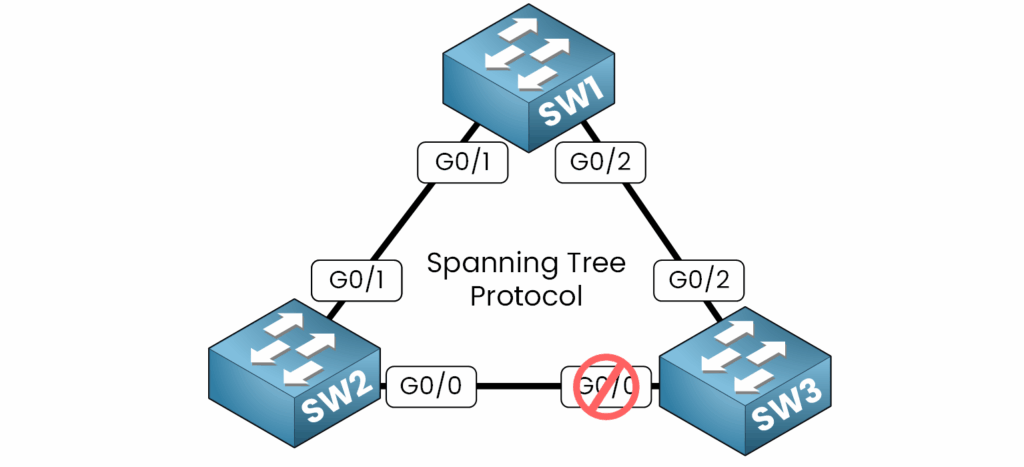
In this network topology with three switches, STP blocks one redundant link to prevent loops. If the active link fails, the previously blocked link becomes active, ensuring uninterrupted communication.
Now, you might wonder : “How does STP determine which paths to block and which to keep active?”
Good question ! It starts by identifying and organizing switches using a unique identifier known as the Bridge ID (BID).
Let’s see how this works.
2. Identifying Switches
To manage redundant paths and organize the network, STP assigns a Bridge ID (BID) to each switch. This unique identifier is used to differentiate switches in the spanning tree topology.
What Is a Bridge ID ?
A Bridge ID consists of:
- Priority + VLAN ID: A configurable priority value combined with the VLAN ID. The default priority value is 32,768
- MAC Address: The unique MAC address of the switch (Example : AABB:CCDD:EE01)

Switch A has the following components for its BID:
- Priority + VLAN ID: 32768 + VLAN 1 = 32769.
- MAC Address: AABB:CCDD:EE01.
The BID for Switch A, 32769.AABB.CCDD.EE01, uniquely identifies it in the network by combining the priority, VLAN, and MAC address.
As you can see in our topology everyone has a different BID !
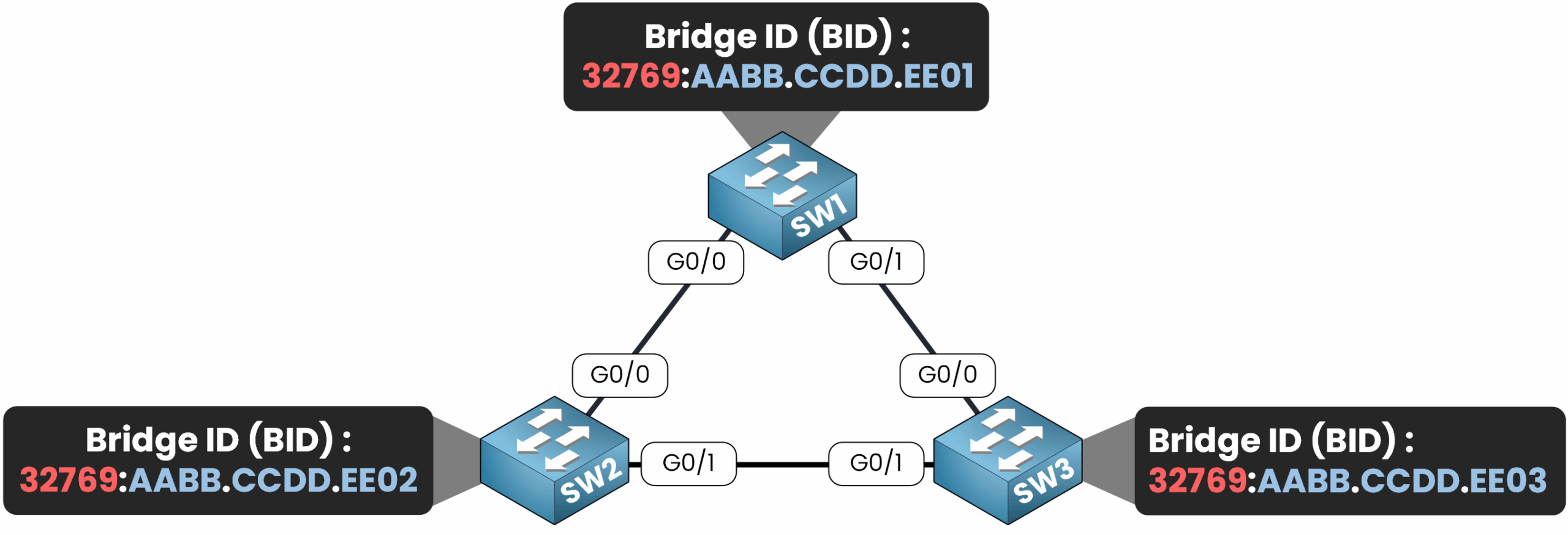
Now that we’ve learned how to identify devices in our Spanning Tree topology using unique identifiers, let’s explore how these devices communicate and exchange information to build and maintain the STP topology.
3. Role of BPDUs
Bridge Protocol Data Units (BPDUs) are messages exchanged between switches in a Spanning Tree topology. They allow switches to communicate their Bridge ID (BID) and share essential information about the network.
BPDUs are STP messages that switches use to exchange information about the network topology, ensuring all devices work together to prevent loops. These messages are essential for electing the Root Bridge which serves as the central point of the spanning tree.
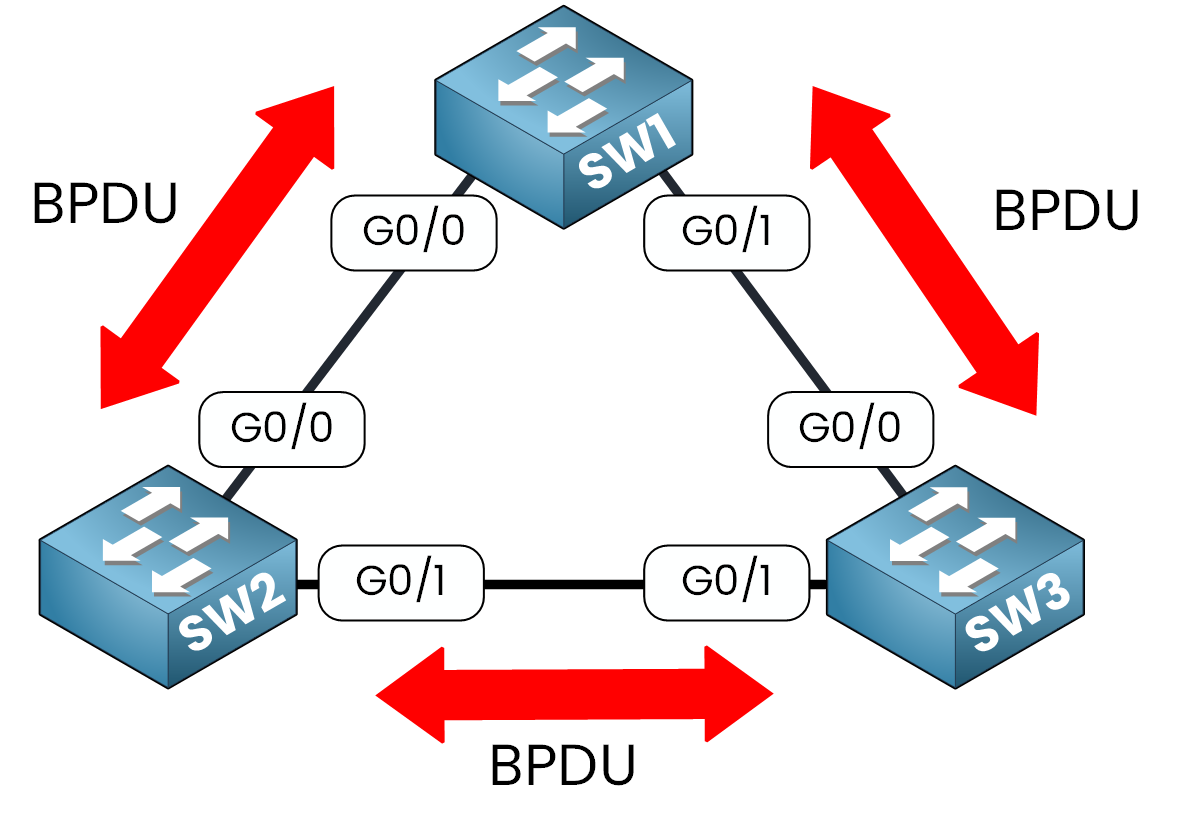
What Do BPDUs Contain?
BPDUs carry essential information that helps switches determine their roles and relationships within the network:
- Root Bridge ID: Identifies the current Root Bridge, the most important device in the Spanning Tree topology.
- Sender’s Bridge ID: Contains the BID of the switch sending the BPDU. This is used to compare with other BIDs and identify the Root Bridge.
- Path Cost: Represents the cumulative cost to reach the Root Bridge from the sender. This value helps switches select the most efficient path to the Root Bridge.
Now that you understand how switches exchange topology information through BPDUs, let’s move on to the four-step process to create the loop-free topology
4. The Election Process
Now that you understand how switches exchange topology information through BPDUs, let’s move on to electing the Root Bridge.
STP establishes a loop-free topology through a systematic four-step process:
- Elect the Root Bridge.
- Identify Root Ports
- Determine Designated Ports
- Assign Blocked Ports
Step 1: Electing the Root Bridge
The Root Bridge serves as the central reference point in the Spanning Tree topology. All switches calculate the shortest path to the Root Bridge to decide which ports remain active and which are blocked.
The election of the Root Bridge is based on the Bridge ID (BID) and occurs through the exchange of BPDUs.
Initial Assumption: Every Switch Thinks It’s the Root
At the start, each switch assumes it is the Root Bridge and advertises its own Bridge ID through BPDUs.

Example :
- SW1 advertises 32769:AABB.CCDD.EE01.
- SW2 advertises 32769:AABB.CCDD.EE02.
- SW3 advertises 32769:AABB.CCDD.EE03.
Initially, all switches claim, “I am the Root Bridge,” as indicated in the BPDUs sent to their neighbors.
BPDU Exchange: Comparing Bridge IDs
Switches exchange BPDUs to compare their Bridge IDs and identify the switch with the lowest BID. This switch becomes the Root Bridge.
Key Criteria for Comparison:
- Priority: The switch with the lowest priority value wins.
- Default priority: 32,768 + VLAN ID.
- Administrators can manually adjust this value to influence the election.
- MAC Address: If two switches have the same priority, the switch with the lowest MAC address is elected as the Root Bridge.
Example:
- SW1 has a BID of 32769:AABB.CCDD.EE01.
- SW2 has a BID of 32769:AABB.CCDD.EE02.
- SW3 has a BID of 32769:AABB.CCDD.EE03.
After comparison:
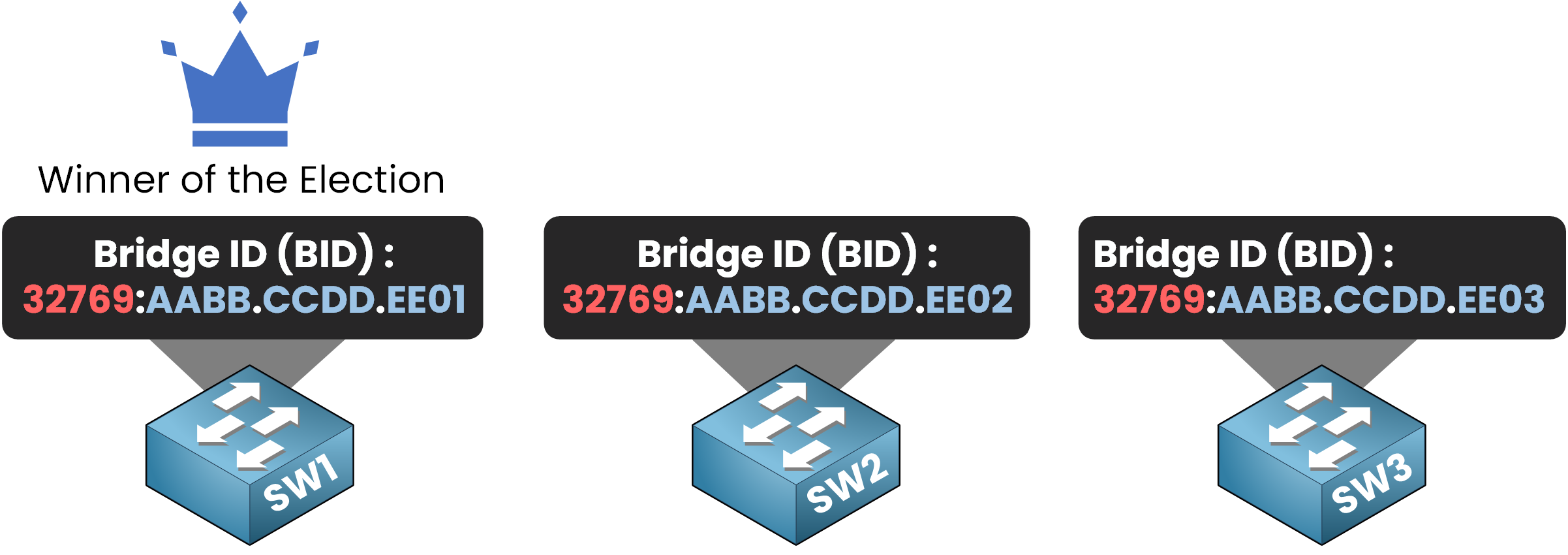
The Spanning Tree topology concludes that SW1 is the Root Bridge because it has the lowest BID.
Root Bridge Selection
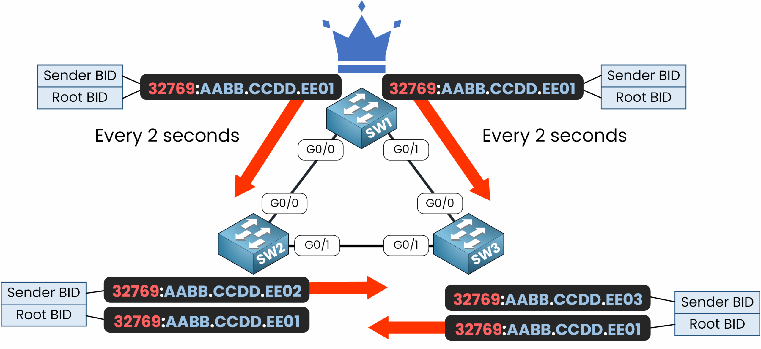
Once the comparison is complete, the switch with the lowest BID is declared the Root Bridge, and all other switches update their BPDUs to reflect the Root Bridge’s BID.
Root BID Example:
- The Root BID is now 32769:AABB.CCDD.EE01 which is acknowledged by all switches in the network.
What Happens After the Root Bridge Is Elected?
- Once the Root Bridge is elected, it becomes the only switch that generates BPDUs to announce its BID at regular intervals (based on the Hello Time).
- Non-root switches:
- Forward the BPDUs received from the Root Bridge to their neighbors.
- Include the Root BID in the forwarded BPDU.
- Identify themselves using their own Sender BID in the BPDU.
This process ensures that all switches remain aware of the current Root Bridge and maintain the topology accordingly.
5. Conclusion
If you’re asking how Spanning Tree Protocol works, here’s a clear summary:
- 🟢 Prevents switching loops by selectively blocking redundant paths in the network.
- 🟢 Elects a Root Bridge to serve as the central reference for all path calculations.
- 🟢 Determines best paths using Bridge ID and path cost to ensure only the optimal links stay active.
- 🟢 Provides automatic failover: when an active link goes down, a previously blocked path is immediately activated.
- 🟢 Ensures loop-free and stable network communication in redundant Layer 2 topologies.
Understanding how Spanning Tree Protocol works is essential to build reliable enterprise networks. In the next lesson, we’ll see exactly how to configure Spanning Tree Protocol to apply these concepts in practice.
